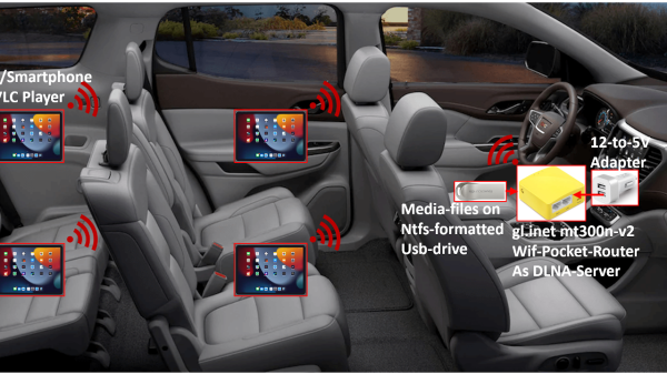
A diagram from the article, showing the router being used in a car for streaming media to multiple portable devices at once

A Portable DLNA Server Hack Helps You Tame OpenWRT

A good amount of hacks can be done with off-the-shelf hardware – what’s more, it’s usually available all over the world, which means your hacks are easier to build for others, too. Say, you’ve built something around a commonly available portable router, through the magic of open-source software. How do you make the fruits of your labour easy to install for your friends and blog readers? Well, you might want to learn a thing or two from [Albert], who shows us a portable DLNA server built around a GL-MT300N-V2 pocket router.

[Albert]’s blog post is a tutorial on setting it up, with a pre-compiled binary image you can flash onto your router. Flash it, prepare a flash drive with your media files, connect to the WiFi network created by the router, run the VLC player app, and your media library is with you wherever you go.

Now, a binary image is good, but are you wondering how it was made, and how you could achieve similar levels of user-friendliness in your project? Of course, here’s the GitHub repository with OpenWRT configuration files used to build this image, and build instructions are right there in the README. If you ever needed a reference on how to make commonly available OpenWRT devices do your bidding automagically, this is it.

This is an elegant solution to build an portable DLNA server that’s always with you on long rides, and, think of it, it handily beats a typical commercialized alternative, at a lower cost. Want software upgrades? Minor improvements and fixes? Security patches? Everything is under your control, and thanks to the open-source nature of this project, you have a template to follow. There won’t always be a perfectly suited piece of hardware on the market, of course, as this elegant dual-drive Pi-based NAS build will attest.

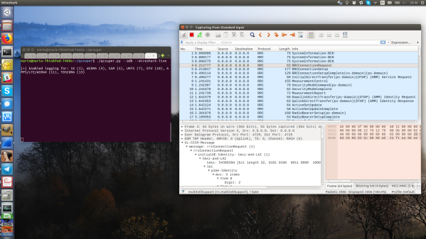
Wireshark screenshot with QCSuper-produced packets streaming into it; QCSuper script running in an adjacent terminal

Turn Your Qualcomm Phone Or Modem Into Cellular Sniffer

If your thought repurposing DVB-T dongles for generic software defined radio (SDR) use was cool, wait until you see QCSuper, a project that re-purposes phones and modems to capture raw 2G/3G/4G/5G. You have to have a Qualcomm-based device, it has to either run rooted Android or be a USB modem, but once you find one in your drawers, you can get a steady stream of packets straight into your Wireshark window. No more expensive SDR requirement for getting into cellular sniffing – at least, not unless you are debugging some seriously low-level issues.

It appears there’s a Qualcomm specific diagnostic port you can access over USB, that this software can make use of. The 5G capture support is currently situational, but 2G/3G/4G capabilities seem to be pretty stable. And there’s a good few devices in the “successfully tested” list – given the way this software functions, chances are, your device will work! Remember to report whether it does or doesn’t, of course. Also, the project is seriously rich on instructions – whether you’re using Linux or Windows, it appears you won’t be left alone debugging any problems you might encounter.

This is a receive-only project, so, legally, you are most likely allowed to have fun — at least, it would be pretty complicated to detect that you are, unlike with transmit-capable setups. Qualcomm devices have pretty much permeated our lives, with Qualcomm chips nowadays used even in the ever-present SimCom modules, like the modems used in the PinePhone. Wondering what a sniffer could be useful for? Well, for one, if you ever need to debug a 4G base station you’ve just set up, completely legally, of course.

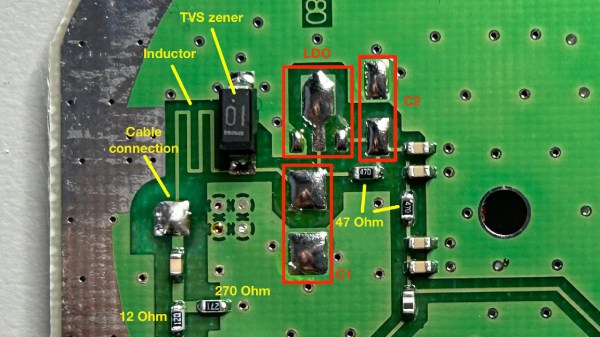
PCB of the antenna about to be modded, with components desoldered and different parts of the circuit highlighted

Make A GPS Antenna Compatible With Same Manufacturer’s Receiver

GPS can be a bit complex of a technology – you have to receive a signal below the noise floor, do quite a bit of math that relies on the theory of relativity, and, adding insult to injury, you also have to go outside to test it. Have you ever wondered how GPS antennas work? In particular, how do active GPS antennas get power down the same wire that they use to send signal to the receiver? Wonder not, because [Tom Verbeure] gifts us a post detailing a mod letting a fancy active GPS antenna use a higher-than-expected input voltage.

[Tom]’s post has the perfect amount of detail – enough pictures to illustrate the entire journey, and explanations to go with all of it. The specific task is modifying a Symmetricom antenna to work with a Symmetricom GPS receiver, which has a puzzling attribute of supplying 12V to the antenna instead of more common 3.3V or 5V. There’s a few possible options detailed, and [Tom] goes for the cleanest possible one – replacing the voltage regulator used inside of the antenna.

With a suitable replacement regulator installed and a protection diode replaced, the antenna no longer registers as a short circuit, and gets [Tom] a fix – you, in turn, get a stellar primer on how exactly active GPS antennas work. If your device isn’t ready to use active GPS antennas, [Tom]’s post will help you understand another GPS antenna hack we covered recently – modifying the Starlink dish to use an active antenna to avoid jamming on the frontlines.

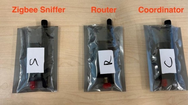
Three ZigBee radios in ESD bags, marked "Zigbee Sniffer", "Router" and "Coordinator".

Crash IoT Devices Through Protocol Fuzzing

IoT protocols are a relatively unexplored field compared to most PC-exposed protocols – it’s bothersome to need a whole radio setup before you can tinker on something, and often, for low-level experiments, just any radio won’t do. This means there’s quite a bit of security ground to cover. Now, the U-Fuzz toolkit from [asset-group] helps us make up for it.

Unlike fuzzers you might imagine, U-Fuzz doesn’t go in blindly. This toolkit has provisions to parse protocols and fuzz fields meaningfully, which helps because many of devices will discard packets they deem too malformed. With U-Fuzz, you feed it a couple packet captures, help it make some conclusions about packet and protocol structure, and get suggestions on how to crash your devices in ways not yet foreseen.

This allows for basically arbitrary protocol fuzzing, and to demonstrate, we get examples on 5G, CoAP and ZigBee probing alike, with a list of found CVEs to wrap the README up. As Wikipedia often states, this list is incomplete, and you can help by expanding it. Fuzzing is an underestimated tool – it will help you hack ubiquitous wireless protocols, proprietary standards, and smart home hubs alike.

PCB Design Review: ESP32-S3 Round LCD Board

For our next installment, I have a lovely and daring PCB submitted by one of our readers, [Vas]. This is an ESP32-S3 board that also has an onboard round TFT display, very similar to the one we used on the Vectorscope badge. The badge is self-sufficient – it has an ESP32, it has a display, a programming connector, two different QWIIC ports you could surely use as GPIOs – what’s not to love?

This is a two-layer board, and I have to admit that I seriously enjoy such designs. Managing to put a whole lot of things into two layers is quite cool in my book, and I have great fun doing so whenever I get the opportunity. There’s nothing wrong with taking up more layers than needed – in fact, if you’re concerned about emitted/received noise or you have high-speed interfaces, four-layer is the way to go. But making complex boards with two layers is a nice challenge, and, it does tend to make these boards cheaper to manufacture as a very nice bonus.

Let’s improve upon it, and support [Vas]’s design. From what I can see looking at this board, we can help [Vas] a lot with ease of assembly, perhaps even help save a hefty amount of money if they go for third-party PCBA instead of sitting down with a stencil – which you could do with this board pretty easily, since all of the components on it, save for the display, are the ones you’d expect JLCPCB to stock.

Continue reading “PCB Design Review: ESP32-S3 Round LCD Board”

Wireless All The Things!

Neither Tom Nardi nor I are exactly young anymore, and we can both remember a time when joysticks were actually connected with wires to the computer or console, for instance. Back then, even though wireless options were on the market, you’d still want the wired version if it was a reaction-speed game, because wireless links just used to be too slow.

Somehow, in the intervening years, and although we never even really noticed the transition as such, everything has become wireless. And that includes our own hacker projects. Sure, the ESP8266 and other WiFi-capable chips made a big difference, but I still have a soft spot in my heart for the nRF24 chipset, which made at least point-to-point wireless affordable and easy. Others will feel the same about ZigBee, but the point stands: nothing has wires anymore, except to charge back up.

The reason? As this experiment comparing the latency of many different wireless connections bears out, wireless data links have just gotten that good, to the point that the latency in the radio is on par with what you’d get over USB. And the relevant software ecosystems have made it easier to go wireless as well. Except for the extra power requirement, and for cases where you need to move a lot of data, there’s almost no reason that any of your devices need wires anymore.

Are you with us? Will you throw down your chains and go wireless?

Benchmarking Latency Across Common Wireless Links For MCUs

Although factors like bandwidth, power usage, and the number of (kilo)meters reach are important considerations with wireless communication for microcontrollers, latency should be another important factor to pay attention to. This is especially true for projects like controllers where round-trip latency and instant response to an input are essential, but where do you find the latency number in datasheets? This is where [Michael Orenstein] and [Scott] over at Electric UI found a lack of data, especially when taking software stacks into account. In other words, it was time to do some serious benchmarking.

The question to be answered here was specifically how fast a one-way wireless user interaction can be across three levels of payload sizes (12, 128, and 1024 bytes). The effective latency is measured from when the input is provided on the transmitter, and the receiver has processed it and triggered the relevant output pin. The internal latency was also measured by having a range of framework implementations respond to an external interrupt and drive a GPIO pin high. Even this test on an STM32F429 MCU already showed that, for example, the STM32 low-level (LL) framework is much faster than the stm32duino one.

Continue reading “Benchmarking Latency Across Common Wireless Links For MCUs”